Introduction to Wave Energy
Published:
Series: Wave Energy Part: 1 (Introduction)
This is the first post in a series on wave energy: what makes it an attractive resource, the physics governing ocean waves, the machines built to extract energy from them, and how wave conditions are actually observed and measured. Later posts in this series move into forecasting; this one lays the groundwork.
Why Wave Energy
The ocean holds a large amount of extractable wave energy. The U.S. Electric Power Research Institute estimates that the United States could harvest about 255 TWh of wave energy per year, roughly 6% of national electricity use. In the United Kingdom, a 2009 assessment put offshore wave resources at 55 TWh annually, around 14% of total national consumption.1
Wave energy is also markedly more consistent than solar or wind. Wind and solar typically generate only 20–30% of the time, while wave energy devices can produce electricity up to 90% of the time — a resource that’s both larger and easier to forecast for grid planning than the other two.2
Compared with fossil-fuel generation, wave energy’s environmental footprint is small. Life-cycle assessments of nearshore wave energy devices show minimal associated emissions, gaseous pollutant output is far below fossil-fuel technologies, with the notable exception of SO₂, where conventional plants can outperform zero-emission combined-cycle gas turbines.1
The Physics of Ocean Waves
Some of this section is adapted from the World Meteorological Organization’s Guide to Wave Analysis and Forecasting.3
Wave energy - also called ocean wave energy, is the renewable energy extracted from the motion of sea-surface waves. Wave energy systems convert the kinetic energy of the vertical movement of ocean waves into useful power.
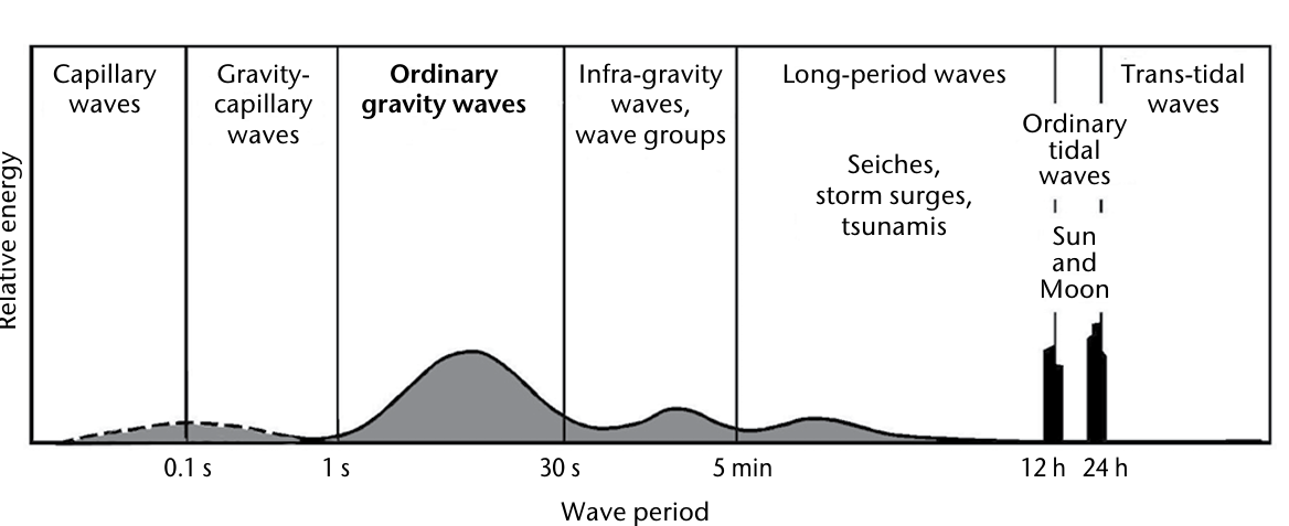
Ocean surface waves arise from several natural forces acting on the sea: atmospheric pressure and wind, earthquakes, gravity from the Earth, Moon, and Sun, the Coriolis effect from Earth’s rotation, and surface tension. Tidal waves sit at the large-scale end of this spectrum, generated by the gravitational pull of the Moon and Sun; capillary waves sit at the opposite end, small waves dominated by surface tension. Gravity waves occur when Earth’s gravity and water buoyancy are the primary restoring forces.
Waves are often described by their period - the time between successive crests passing a fixed point. The type and magnitude of the forces generating a wave are typically reflected in its period, as shown below.
Basic Definitions
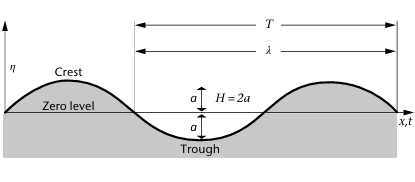
- Wavelength (λ) — the horizontal distance between two consecutive wave crests, in metres.
- **Period (T): **the time, in seconds, between the arrival of one crest and the next at a fixed location.
- Frequency (f): how many crests pass a fixed point each second, in Hertz, equal to 1/T.
- Amplitude (a): the maximum vertical displacement of the water surface from mean sea level.
- Wave height (H): the vertical distance from a crest to the preceding trough. For a sinusoidal wave, H = 2a.
- Propagation speed (c): the rate at which the wave pattern moves forward, also called phase speed or wave speed.
- **Wave steepness: **the ratio between wave height and wavelength, H/λ.
Energy in Waves
Waves carry both kinetic energy (the motion of water particles) and potential energy (the vertical displacement of water), and this energy travels along with the wave. Interestingly, the total energy is always split evenly between the two - the equipartition of energy.
Wave energy doesn’t travel at the phase speed c. Instead, it moves with the group velocity, which in deep water is half the phase speed. The total energy per wavelength of a simple linear wave is:
\[E = \frac{1}{2}\rho g a^2 = \frac{1}{8}\rho g H^2\]where a is amplitude and H is wave height.
Influence of Water Depth
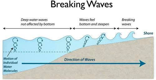
Water particle motion decreases exponentially with depth. If depth exceeds λ/2, the bottom has no influence on the wave, this is deep water. More finely:
- Deep: h > λ/4
- Transitional depth: λ/25 < h < λ/4
- Shallow depth: h < λ/25
In shallow water, wave speed decreases and wavelength shortens, while period stays constant. The dispersion relation becomes depth-dependent:
\[c = \sqrt{\frac{g}{k}\tanh(kh)}\]and in very shallow water this simplifies to:
\[c = \sqrt{gh}\]As waves approach shore, group velocity decreases, so wave height increases - a process known as shoaling.
Wave Energy Converter Devices
The kinetic and potential energy carried by a moving ocean wave is turned into usable mechanical or electrical energy by machines called wave energy converters (WECs). There are eight main recognized types, summarized below.4
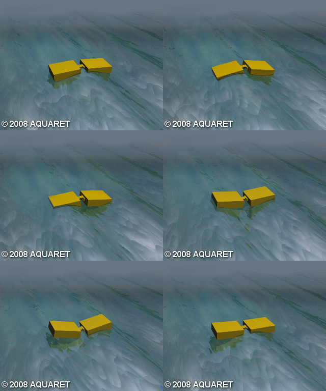
A) Attenuator
A floating device which operates parallel to the wave direction and effectively rides the waves. These devices capture energy from the relative motion of their two arms as the wave passes them.
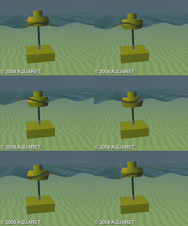
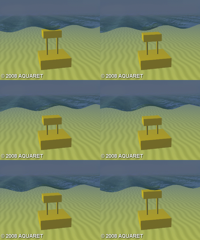
B) Point Absorber
A floating structure which absorbs energy from all directions through its movement at or near the water surface. It converts the motion of the buoyant top relative to the base into electrical power; the power take-off system can take several forms depending on the displacer/reactor configuration.
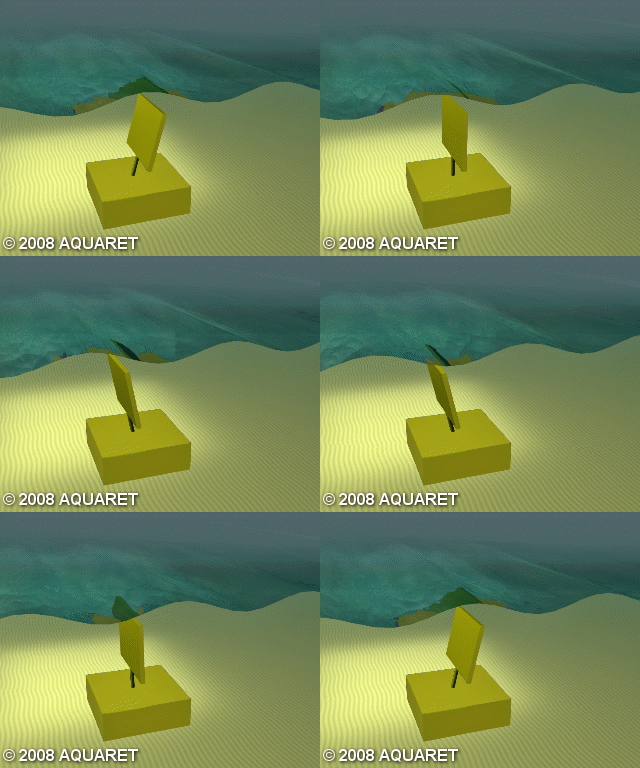
C) Oscillating Wave Surge Converter
Extracts energy from wave surges and the movement of water particles within them. The arm oscillates like a pendulum mounted on a pivoted joint, driven by the movement of water in the waves.
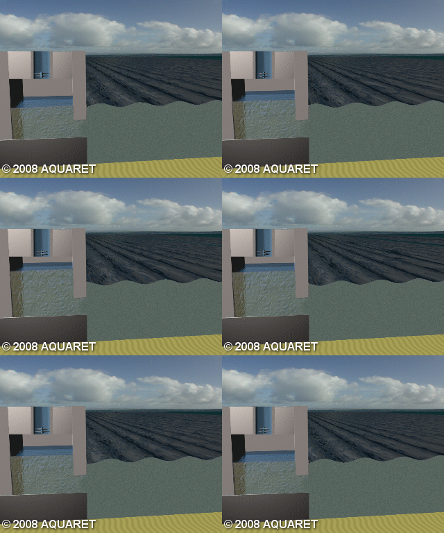
D) Oscillating Water Column
A partially submerged, hollow structure open to the sea below the water line, enclosing a column of air above a column of water. Waves make the water column rise and fall, compressing and decompressing the air, which is forced through a turbine that generates electricity regardless of airflow direction.
E) Overtopping / Terminator Device
Captures water as waves break into a storage reservoir. The water is then returned to the sea through a conventional low-head turbine that generates power; "collectors" may be used to concentrate the wave energy first.
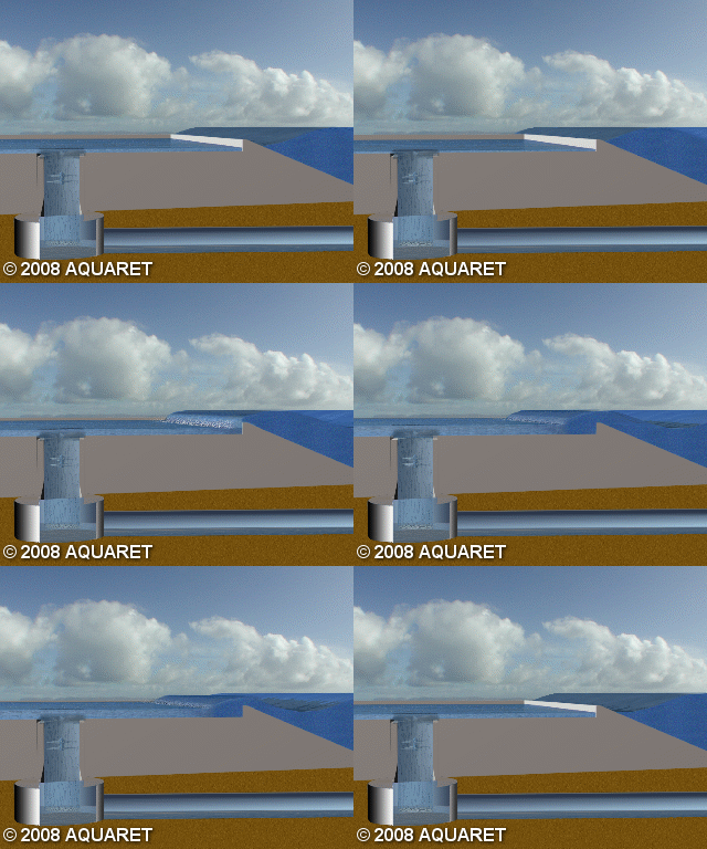
F) Submerged Pressure Differential
Typically located near shore and attached to the seabed. The rise and fall of sea level above the device induces a pressure differential, and the alternating pressure pumps fluid through a system to generate electricity.
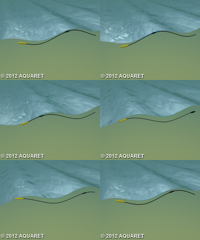
G) Bulge Wave
A rubber tube filled with water, moored to the seabed heading into the waves. Water enters through the stern, and the passing wave causes pressure variations along the tube, creating a "bulge" that grows as it travels, gathering energy that drives a low-head turbine at the bow before the water returns to the sea.
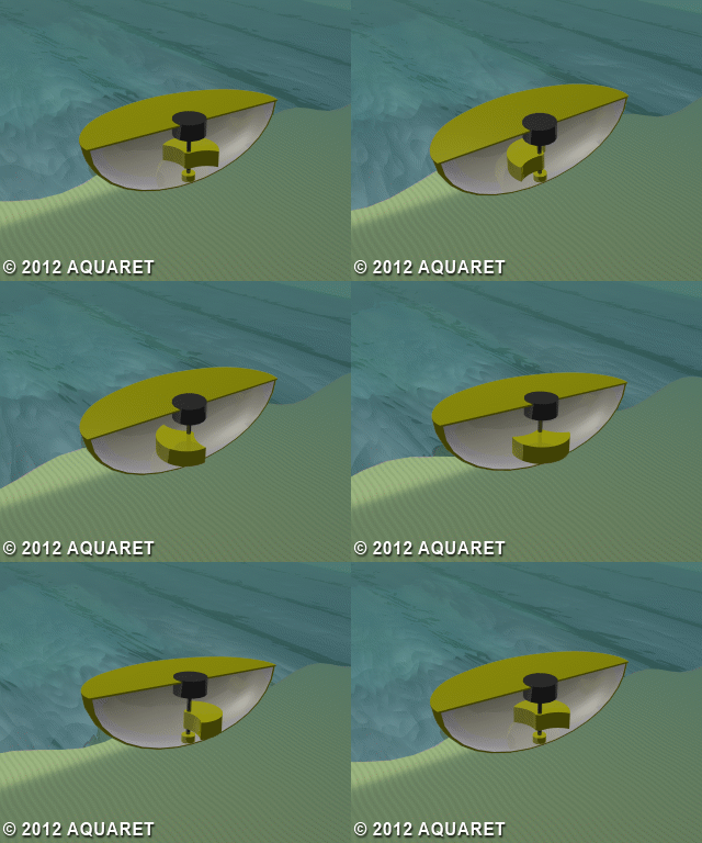
H) Rotating Mass
Captures energy from the device heaving and swaying in the waves, using that motion to drive either an eccentric weight or a precessing gyroscope. In both cases, the moving mass is attached to an electric generator inside the device.
I) Other. This covers devices with a unique design that doesn’t fit the categories above, or where the device’s characteristics couldn’t be determined, for example the Wave Rotor, a turbine turned directly by the waves, or proposed flexible structures whose changing shape/volume is itself part of the power take-off system.
Wave Measurement
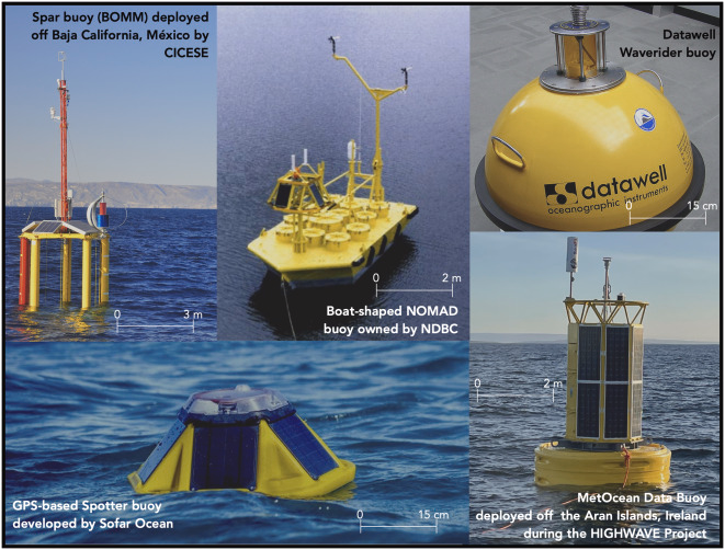
Wave energy measurement relies on a range of observational techniques, each capturing different physical aspects of ocean waves. In-situ instruments — Inertial Measurement Unit (IMU) buoys, GPS buoys, spar buoys, resistance and capacitance wave gauges, pressure sensors, Acoustic Doppler Current Profilers (ADCPs), and hydrophones - provide high-accuracy point measurements of wave kinematics, acoustics, and orbital velocities.
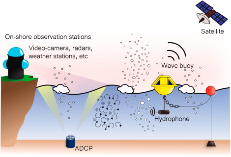
Buoy designs vary widely, each optimized for a specific deployment condition and data requirement. Coastal remote-sensing systems — stereo video-camera systems and X-band marine radars — extend coverage across nearshore regions, while satellite and airborne platforms (Synthetic Aperture Radar, satellite altimeters, CFOSAT, SKIM, SWIM, and airborne lidar) supply global directional and spectral information. Acoustic and environmental methods such as Acoustic Surface Tracking (AST), Acoustic Doppler Velocimeters (ADV), and Sound Pressure Level (SPL) sensing complement these observations in specialized environments.
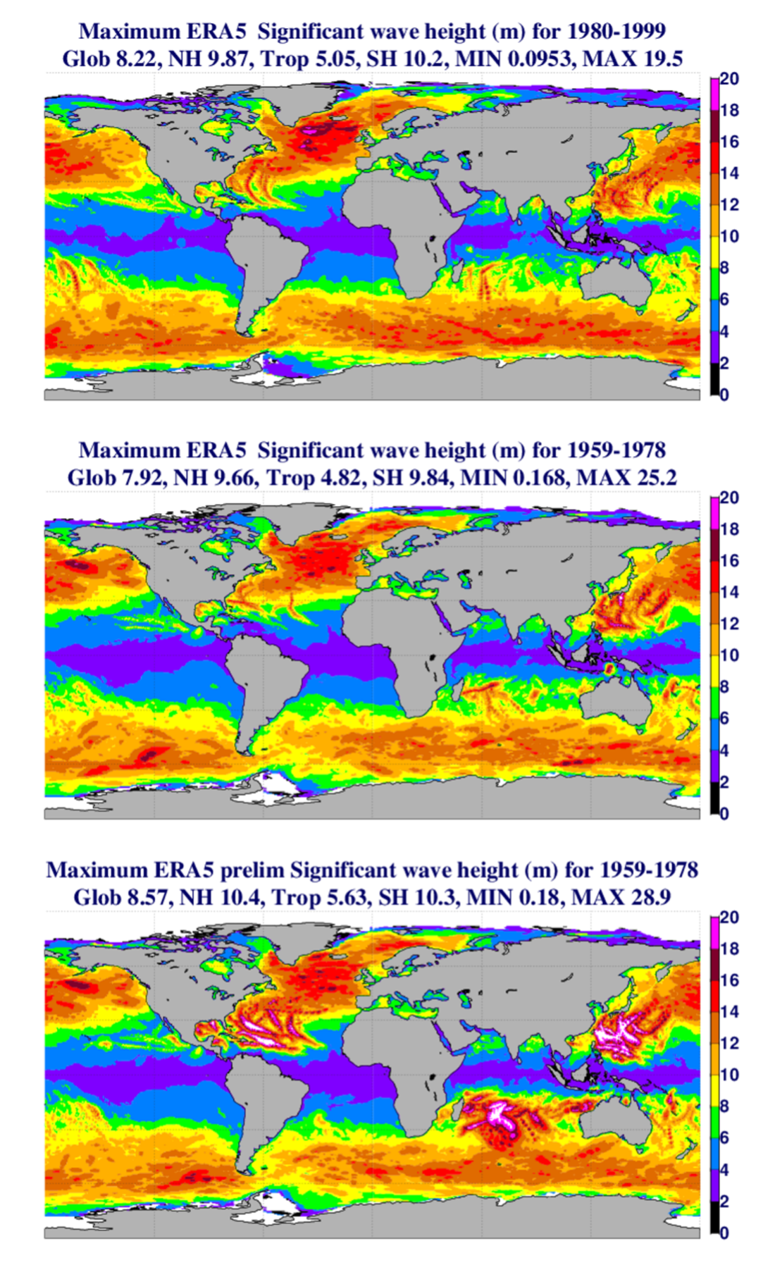
Modern reanalysis products such as ERA5 further complement direct observation, providing globally consistent wave parameters by running the ECMWF WAM spectral wave model and assimilating buoy and satellite observations.
A. Shadmani, B. Golparvar, M. R. Nikoo, A. H. Gandomi, and R.-Q. Wang, “A review of machine learning and deep learning applications in wave energy forecasting and WEC optimization,” Energy Strategy Reviews, vol. 49, p. 101180, 2023. ↩ ↩2
B. Drew, A. R. Plummer, and M. N. Sahinkaya, “A review of wave energy converter technology,” Proc. Inst. Mech. Eng. Part A: J. Power Energy, vol. 223, no. 8, pp. 887–902, 2009, doi: 10.1243/09576509JPE782. ↩
World Meteorological Organization, Guide to Wave Analysis and Forecasting, 3rd ed., WMO-No. 702, Geneva, Switzerland: WMO, 2018. ↩
EMEC — European Marine Energy Centre, “Wave Devices”. ↩