Heat Pump Digital Twins: Modeling and Hybrid State Estimation
Published:
1. Introduction to Heat Pump Technologies
A heat pump is an energy-efficient device that provides climate control by moving heat from one location to another using electricity and a refrigerant circuit, rather than generating heat by burning fossil fuels. In winter, it extracts thermal energy from the ambient air, ground, or water sources to heat a building. In summer, the cycle reverses, removing heat from the indoor air and exporting it outside, operating exactly like an air conditioner. (Source: Carrier)
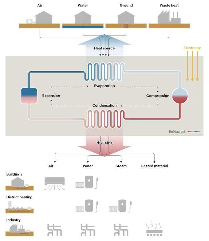
Beyond residential spaces, heat pumps meet heating requirements in commercial buildings and industrial applications, delivering hot air, hot water, or steam. Large-scale heat pumps integrated into industrial processes or district heating networks often require higher input temperatures. These systems frequently extract thermal energy from waste heat sources, such as data centers, wastewater treatment plants, and industrial exhaust streams. (Source: IEA)
2. Thermodynamic Advantages and Disadvantages
(Note: Data and advantages synthesized from the Leonardo da Vinci project ENERSOL report: Energy Saving and Renewable Energy in Vocational Education)
2.1 Advantages
- Energy Efficiency: Heat pumps reduce electricity consumption by approximately $70\%$ compared to direct resistance electric heating. While conventional electric heaters convert electricity directly into heat at a $1:1$ ratio, heat pumps use electricity only to drive the compressor, extracting the remaining thermal energy from the environment.
- Economic Savings: By using less electricity to deliver the same heating load, operational energy costs are significantly lower than resistance heating. Actual financial savings depend on local fuel tariffs, capital investment costs, and state subsidies.
- Environmental Impact: Lower electricity demand reduces primary energy requirements and the associated emissions from power plants. Transitioning to heat pumps can reduce local $\text{NO}_x$ emissions by up to $70\%$ and $\text{SO}_2$ emissions by up to $30\%$.
2.2 Disadvantages
- Initial Capital Investment: The primary drawback of heat pump systems is their high upfront cost, leading to typical payback periods of 6 to 8 years. The exact return on investment depends on the building’s current insulation levels, the low-temperature heat source chosen, and government incentives.
3. Working Principles and Classifications
Heat pumps generally fall into two categories: vapour compression systems and absorption systems. (Source: JICA Report)
3.1 Vapour Compression Systems
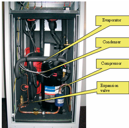
Most heat pumps operate on a closed vapour compression cycle. The system consists of four primary components: an evaporator, a compressor, a condenser, and an expansion valve.
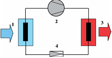
The working fluid (refrigerant) circulates continuously through these components:
- Evaporator (1): The refrigerant is kept at a temperature lower than the external heat source, causing heat to transfer into the fluid and boil it into a low-pressure vapour.
- Compressor (2): The vapour is compressed, increasing its pressure and temperature. The compressor is the primary consumer of electrical energy in the system, typically driven by an electric motor.
- Condenser (3): The hot, high-pressure vapour enters the condenser, where it releases its latent heat to the building’s heating circuit, condensing back into a liquid state.
- Expansion Valve (4): The high-pressure liquid refrigerant passes through the expansion valve, dropping in pressure and temperature back to the evaporator levels, completing the cycle.
3.2 Absorption Heat Pumps
Unlike mechanical vapour compression systems, absorption heat pumps are thermally driven. Instead of using mechanical work (a compressor) to increase refrigerant pressure, they use high-temperature heat (from gas combustion, steam, or industrial waste heat).
Absorption systems rely on the chemical affinity between a refrigerant and an absorbent. Common pairs include:
- Water (refrigerant) and Lithium Bromide (absorbent)
- Ammonia (refrigerant) and Water (absorbent)
The compression stage is replaced by a thermal circuit containing an absorber, a solution pump, a generator, and an expansion valve:
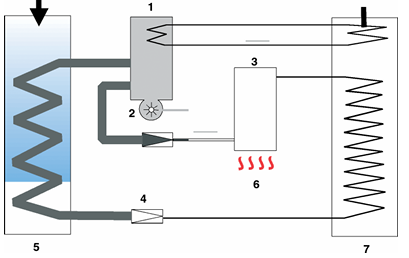
- Low-pressure refrigerant vapour from the evaporator is absorbed by the absorbent liquid in the absorber (1), releasing absorption heat.
- The liquid mixture is pumped to high pressure using a small solution pump (2) (requiring minimal electrical power).
- The pressurized mixture enters the generator (3), where external heat boils off the refrigerant vapour from the absorbent.
- The separated refrigerant vapour moves to the condenser to release useful heat, while the concentrated absorbent returns to the absorber via an expansion valve (4).
4. Key Performance Parameters
4.1 Coefficient of Performance (COP)
The efficiency of a heat pump is measured by the Coefficient of Performance (COP), defined as the ratio of useful heat output to the electrical energy input:
\[\text{COP} = \frac{Q_{\text{output}}}{W_{\text{input}}}\]Typical COP values range from $2.5$ to $4.0$, meaning that $1\text{ kWh}$ of electricity yields $2.5$ to $4.0\text{ kWh}$ of heat. The COP is not static; it is highly dependent on the temperature difference between the heat source and the target heating system. A smaller temperature difference results in a higher COP because the compressor works less.
We can approximate COP variation with outdoor temperature using a linear model:
\[\text{COP}(T_{\text{amb}}) = \text{COP}_0 + \alpha \cdot (T_{\text{amb}} - 5)\]Where:
- $\text{COP}_0$ is the baseline COP at $5^\circ\text{C}$ (e.g., $3.0$).
- $\alpha$ is the temperature coefficient (e.g., $0.05$).
4.2 Heating Power
The total heating power delivered to the condenser is the sum of the environmental heat extracted by the evaporator and the electrical power converted into heat during compression:
\[\Phi_H = Q_{\text{evaporator}} + W_{\text{compressor}}\]4.3 Seasonal Performance Factor (SPF)
While the COP measures efficiency at a specific operating point, the Seasonal Performance Factor (SPF) describes the heat pump’s efficiency aggregated over an entire season. It accounts for variable heating and cooling loads, changing outdoor air/source temperatures, and auxiliary energy consumption over the year.
5. Heat Pump Configurations
Heat pumps are classified by their source and sink mediums:
5.1 Air-to-Water
Extracts heat from ambient outdoor air (or ventilation exhaust air) and transfers it to a water-based central heating loop. These systems are popular due to lower installation costs, but their efficiency drops during cold winter days.
5.2 Water-to-Water
Uses groundwater, surface water, or wastewater as the heat source. Because water temperatures remain relatively stable throughout the winter, these heat pumps maintain high efficiency, though they require access to a reliable water source.
5.3 Ground-to-Water (Geothermal)
Draws heat from the ground via horizontal pipe loops (buried 1–2 meters deep) or vertical boreholes (up to 100 meters deep). Antifreeze fluid circulates through the ground loop to absorb thermal energy, providing high and stable COPs year-round.
6. Digital Twins for Heat Pump Systems
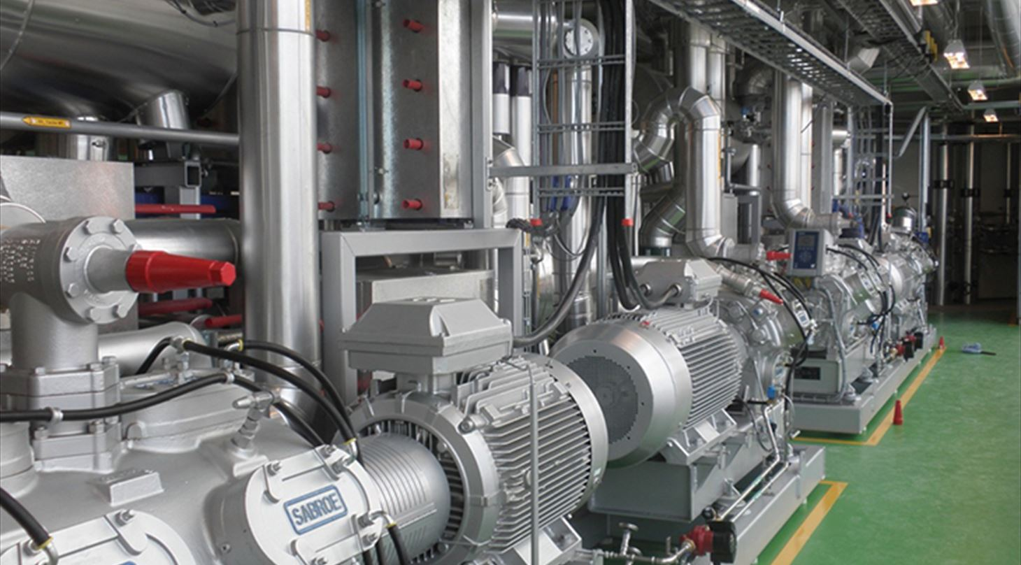
A Digital Twin is a virtual, numerical representation of a physical system that adapts to its real-world counterpart. By continuously processing operational data, digital twins enable real-time state estimation, fault detection and diagnosis, predictive maintenance, and optimized control. (Source: Danish Technological Institute)
6.1 Hybrid State Estimation
A common strategy in district heating is deploying a hybrid digital twin. This approach combines a physics-based baseline model with a machine-learning model that learns the residual errors.
The physics layer models the thermal dynamics of the system (e.g., a storage tank or thermal loop) using a differential energy-balance equation:
\[C \frac{dT}{dt} = Q_{\text{hp}} - Q_{\text{demand}} - Q_{\text{loss}}\]Where:
- $C$ is the thermal heat capacity.
- $Q_{\text{hp}}$ is the heat input from the heat pump.
- $Q_{\text{demand}}$ is the network thermal load.
- $Q_{\text{loss}}$ is the thermal loss to the ambient environment.
While this physics model ensures thermodynamic consistency (mass and energy conservation), it struggles with unmodeled dynamics, such as insulation degradation or sensor drift.
To correct these errors, a machine-learning model (such as LightGBM) is trained to predict the temperature residual ($T_{\text{measured}} - T_{\text{physics}}$). During operation, the final state estimate is obtained by combining both predictions:
\[T_{\text{corrected}} = T_{\text{physics}} + f_{\text{ML}}(\text{measured features})\]This hybrid approach ensures the digital twin remains structurally grounded by physics while retaining the flexibility to adapt to real-world deviations.
References
- Carrier Corporation: What Is A Heat Pump And How Does It Work?
- International Energy Agency (IEA): How a heat pump works – The Future of Heat Pumps Analysis
- Leonardo da Vinci project ENERSOL: EU Heat Pumps – Energy Saving and Renewable Energy in Vocational Education Report.
- Japan International Cooperation Agency (JICA): Vapour Compression and Absorption Systems Technical Report
- Danish Technological Institute: Digital twins for large-scale heat pumps and refrigeration systems
The next post will explore Reinforcement Learning for smart heat pump control within this digital twin framework.